43 Results
View results:
Sort by:

Our webservice offers users the opportunity to communicate with RFEM 6 and RSTAB 9 using various programming languages. Dlubal's high-level functions (HLFs) allow you to expand and simplify the WebService's functionality. In line with RFEM 6 and RSTAB 9, using our WebService makes the engineer's work easier and faster. Check it out now! This tutorial shows you how to use the C# library by means of a simple example.

Custom sections are often required in cold-formed steel design. In RFEM 6, the custom section can be created using one of the “Thin-Walled” sections available in the library. For other sections that do not meet any of the 14 available cold-formed shapes, the sections can be created and imported from the standalone program, RSECTION. For general information on AISI steel design in RFEM 6, refer to the Knowledge Base article provided at the end of the page.

Steel connections in RFEM 6 can be created by simply entering predefined components in the Steel Joints add-on. The collection of these components is constantly being improved to make your work even easier even when modeling steel connections. In this article, the connection plate component is introduced as a component recently added to the add-on's library.

Surfaces in building models can be of many different sizes and shapes. All surfaces can be considered in RFEM 6 because the program allows to define different materials and thicknesses as well as surfaces with different stiffness and geometry types. This article focuses on four of these surface types: rotated, trimmed, without thickness, and load transfer.

Spreadsheet programs like MS EXCEL are very popular with engineers because they allow you to simply automatize your calculations and quickly output the results. Therefore, combining MS EXCEL used as a graphical interface with Dlubal's WebService API is an obvious choice. By using the free xlwings library for Python, you can control EXCEL, and read and write values. The functionality is described in the following, using an example.

In RFEM 6 it is possible to define multilayer surface structures with the help of the “Multilayer Surfaces” add-on. Hence, if you have activated the add-on in the model’s Base Data, it is possible to define layer structures of any material model. You can also combine material models of, for example, isotropic and orthotropic materials.
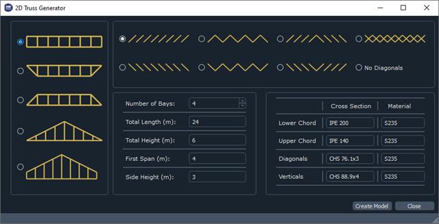
The recently introduced Webservices gives users the ability to communicate with RFEM 6 using their programming language of choice. This feature is enhanced with our High Level Functions (HLF) Library. The libraries are available for Python, JavaScript, and C#. This article looks at a practical use case of programming a 2D Truss Generator with Python. "Learning by doing," as the saying goes.

The stand-alone program RSECTION is at your disposal for determining section properties and performing stress analysis for thin-walled and massive cross-sections. The program can be connected to both RFEM and RSTAB so that sections from RSECTION are also available in the RFEM and RSTAB library. Likewise, internal forces from RFEM and RSTAB can be imported into RSECTION.

The advantage of the RFEM 6 Steel Joints add-on is that you can analyze steel connections using an FE model for which the modeling runs fully automatically in the background. The input of the steel joint components that control the modeling can be done by defining the components manually, or by using the available templates in the library. The latter method is included in a previous Knowledge Base article titled “Defining Steel Joint Components Using the Library". The definition of parameters for the design of steel joints is the topic of the Knowledge Base article “Designing Steel Joints in RFEM 6".

Steel connections in RFEM 6 are defined as an assembly of components. In the new Steel Joints add-on, universally applicable basic components (plates, welds, auxiliary planes) are available for entering complex connection situations. The methods with which connections can be defined are considered in two previous Knowledge Base articles: “A Novel Approach to Designing Steel Joints in RFEM 6" and “Defining Steel Joint Components Using the Library".

You can use the Steel Joints add-on in RFEM 6 to create and analyze steel connections using an FE model. You can control the modeling of the connections via a simple and familiar input of components. Steel joint components can be defined manually, or by using the available templates in the library. The former method is included in a previous Knowledge Base article titled “A Novel Approach to Designing Steel Joints in RFEM 6". This article will focus on the latter method; that is, it will show you how to define steel joint components using the available templates in the program’s library.

Steel has poor thermal properties in terms of fire resistance. The thermal expansion for increasing temperature is very high compared to that of other building materials, and might result in effects that were not present in the design at normal temperature due to restraint in the component.As temperature increases, steel ductility increases, whereas its strength decreases. Since steel loses 50% of its strength at temperature of 600 °C, it is important to protect components against fire effects. In the case of protected steel components, the fire resistance duration can be increased due to the improved heating behavior.

This article describes how a flat slab of a residential building is modeled in RFEM 6 and designed according to Eurocode 2. The plate is 24 cm thick and is supported by 45/45/300 cm columns at distances of 6.75 m in both the X and Y directions (Image 1). The columns are modeled as elastic nodal supports by determining the spring stiffness based on the boundary conditions (Image 2). C35/45 concrete and B 500 S (A) reinforcing steel are selected as the materials for the design.

Rolled sections, the most common cross‑section type in RFEM and RSTAB, can also have user‑defined parameters. To do this, select the cross‑section to be modified in the cross‑section library and click the [Parametric Input...] button.
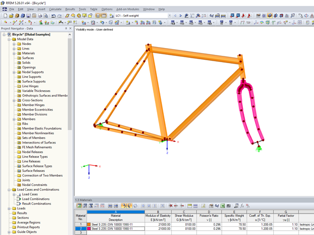
In RFEM and RSTAB, you can simulate extensive complex models from different materials in one computing environment.
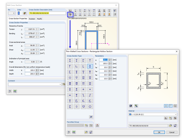
If you define a parametric cross-section in the library using its dimensions, the geometric properties are coded in the cross-section description; for example, "TO 200/100/10/10/10/10".
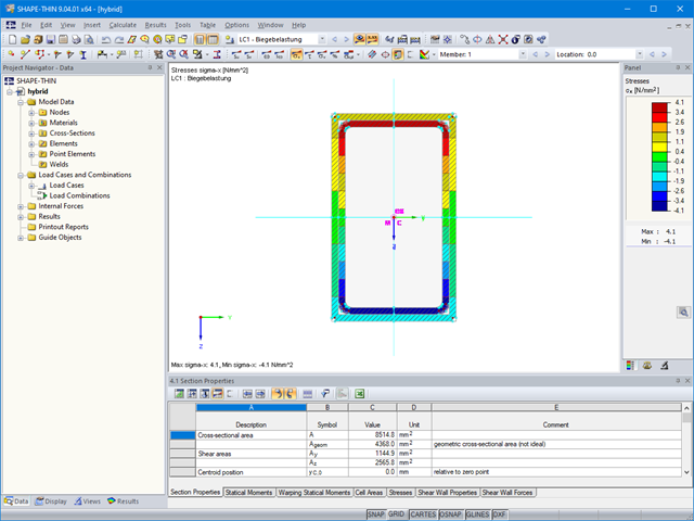
The material allocation for hybrid SHAPE‑THIN cross‑sections can be selected easily in RFEM and RSTAB. The prerequisite for this is the allocation of different materials to the cross‑section elements in SHAPE‑THIN.

In RFEM and RSTAB, you can visually check or display the materials used for members in the wireframe and solid models.

In the age of BIM, data exchange between the various disciplines of structural engineering is becoming increasingly important. Since each software has its own specifications with regard to the description of cross-sections and materials, RFEM and RSTAB offer a conversion table (mapping file).

The RF‑/STEEL EC3 add-on module can perform the design of fillet welds for all parametric, welded cross-sections of the cross-section library. For this, the option must be activated in the detail settings of the module. As an alternative, you can also use a surface model for the design.
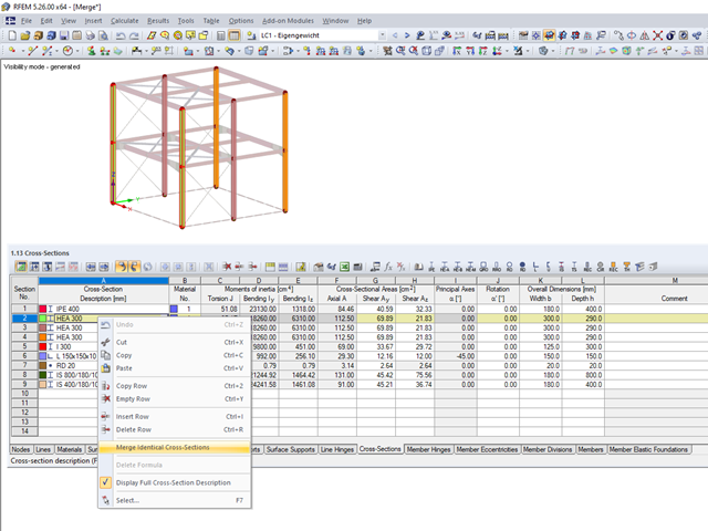
When modeling more complex structures with an increased degree of repetition, identical material and cross-section definitions often occur.

When calculating foundations according to EC 7 or EC 2, different foundation types or sizes are usually used in one object. However, boundary conditions like the soil parameters, the materials for foundations, concrete covers, and the load combinations selected for design remain the same for all foundations, as a rule.
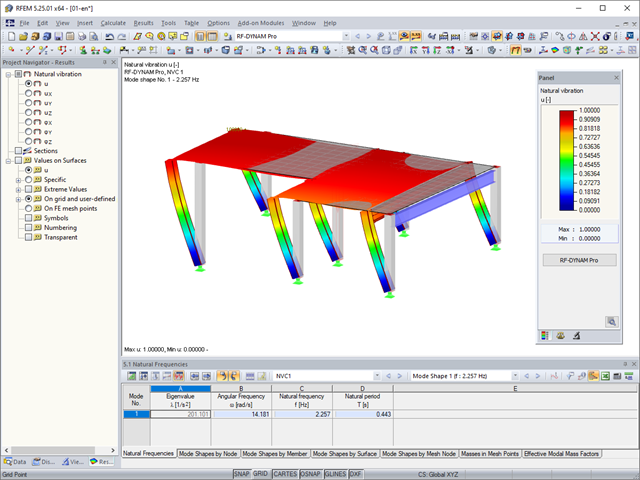
In RFEM, you can modify stiffnesses for materials, cross-sections, members, load cases, and load combinations in many places. There are two options in RF‑DYNAM Pro for considering these modifications when determining the natural frequencies.
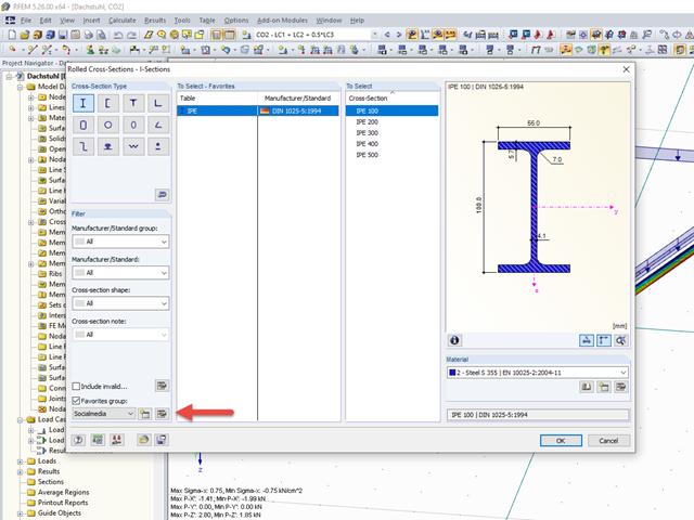
The cross-section library in RFEM 5 and RSTAB 8 offers the option to save certain cross-section selections in different favorites groups.
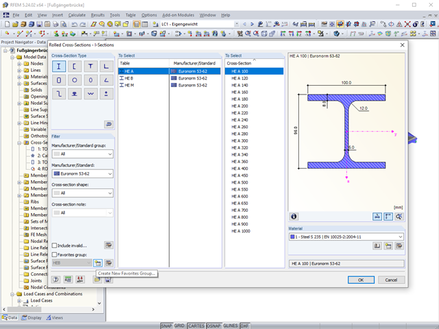
The "Filter" option in the cross‑section library allows you to show only cross‑sections of certain standards, shapes, or types. In the same window, you can also select the material.

The elastic deformations of a structural component due to a load are based on Hooke's law, which describes a linear stress-strain relation. They are reversible: After the relief, the component returns to its original shape. However, plastic deformations lead to irreversible deformations. The plastic strains are usually considerably larger than the elastic deformations. For plastic stresses of ductile materials such as steel, yielding effects occur where the increase in deformation is accompanied by hardening. They lead to permanent deformations - and in extreme cases to the destruction of the structural component.
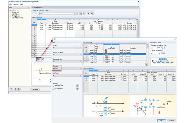
Design loads specified in the AASHTO Bridge Design Specification are available in the RF-MOVE Surfaces moving load library. Design Truck (HS-20), Tandem, Type 3, and Overload are available options.
![[Edit Parameters] Button in Table Toolbar](/en/webimage/009362/2418341/01-en-png.png?mw=640&hash=c76563b459152b19c98197ea6ba342be89d9a5bc)
The SHAPE‑THIN stand-alone program determines the characteristic values and stresses of any thin‑walled cross‑sections. Graphic tools and features allow for modeling complex cross‑section shapes. In addition to the graphical input, it is also possible to enter the data in tables. As an alternative, you can import a DXF file and use it as a basis for further modelling. Also, each cross-section can be entered using the cross-section library of Dlubal Software and combined as a part with the user-defined elements.
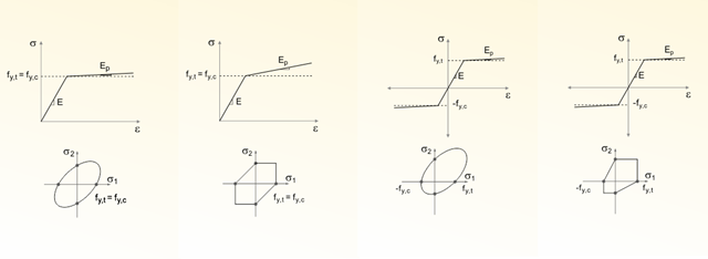
One of my earlier articles described the Isotropic Nonlinear Elastic material model. However, many materials do not have purely symmetrical nonlinear material behavior. In this regard, the yield laws according to von Mises, Drucker-Prager and Mohr-Coulomb mentioned in this previous article are also limited to the yield surface in the principal stress space.
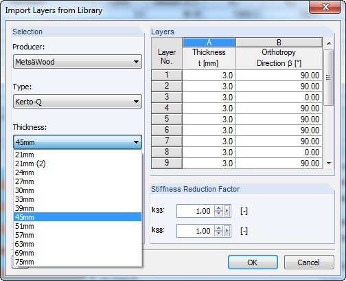
The RF‑LAMINATE library now includes the Kerto‑Q product by the company Metsä Wood. All LVL panels are available, including the characteristic strength parameters.